Casting Porosity Inspection Standards
Introduction to VW50093 and PV6093
Today we introduce Volkswagen’s standards for casting porosity. These standards of Volkswagen are more detailed and meticulous. They have typical reference significance, and many other companies also refer to this standard to detect castings.
VW50093 is the latest porosity standard by Volkswagen, while their tested standard is PV6093
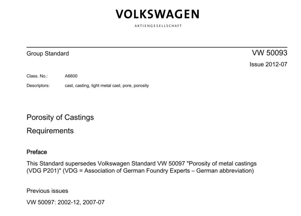
1.Porosity Requirements for Metal Parts (VW50093) Application:
The VW50093 standard is suitable for all metal castings (ferrous and non-ferrous) and various casting methods. If approved by the relevant laboratory, one can also apply it to non-metal injection molding parts.
However, it’s best to add relevant notes to the drawing at this time. (This version replaces the 2007 version VW50097). For die casting, this standard is still very suitable.
2.Introduction to the Old Standard VW50097 Porosity Parameter
The items covered by the standard includes:
Pore Class: Described according to load type:
S – for parts that are primarily subject to static loads
D – for parts that are primarily subject to dynamic loads
F – Used for parts with special requirements for functional surfaces
Porosity: The percentage of porosity in parts with different load types S, D, F, G.
Pore grade S – starts from S5 and increases in multiples of 5; less than S5 does not exist. Such as S5, S10, S15
Pore grades D-D1 to D4 increase in integer multiples, from D5 onwards in integer multiples of 5, and D0 does not exist. Such as D1 D2 D3 D5 D10 D15
Pore grade F-increases in integer multiples from F0, and n in pore size Pn increases by 0.1mm, but the drawing requirements cannot be less than 0.2mm.
Pore grade G – starting from G0 and increasing in integer multiples.
G – for parts without special requirements
Diameter of the hole: this is the maximum allowable diameter (mm) of a single air hole. This parameter is incremented by 0.5mm, but the drawing requirements cannot be less than 0.5mm.
Additional items
An: The minimum distance between two adjacent holes A=n*Ф (Ф is the diameter of the smaller air hole)
M: Coarse pores are only allowed in the center of the wall thickness of the part
C: Coarse pores are only allowed to appear in the accumulation (hot node) part of the material
R: The porosity (D10-D30) is only applicable to the central third of the wall thickness, and the requirement for the outer third is D4. D represents porosity class D, parts subject to dynamic loads. Numbers indicate the percentage of pore area.
Pn: The maximum allowable pore size is only applicable to the central one-third area of the wall thickness. The pore diameter in the third outer area must be less than n (but in the case of load category F, you can ignore pores less than n.
Selection of porosity grade datum:
– Allowed datum shapes are: square, triangle, and circle
– The datum plane should be chosen so that the datum plane covers the largest area possible!
Example: VW-50097-S5/1.5/M
– where VW-50097 indicates the standard used.
– S5 represents the part carrying the static load, the area of the maximum porosity allowed = 5%
– 1.5 means the maximum allowable porosity is 1.5mm in diameter.
– M for additional: Coarse pores are only allowed in the center of the wall thickness of the part.
Example: VW50097-D10-1.5-R
– Standard used for VW50097 annotation.
– D in D10 means the part used to carry the dynamic load, 10 means the area of the maximum porosity allowed = 10%.
– 1.5 means the maximum air hole diameter allowed is 1.5mm.
– R is the content of the R item in the additional item.
Example: VW-50097-G5/2/C
– Standard used for VW50097 annotation.
– G in G5 means that there are no special requirements for the type of load, and 5 means that the area of the maximum pore allowed = 5%
– 2 means the maximum allowable single hole diameter is 2mm
– C indicates an additional item; a hole pocket is allowed at the hot node.
Example: VW50097-F4/1/A2/P0.2
– Standard used for VW50097 annotation.
– F in F4 means that the functional surface of the part has special requirements, and 4 means that at most 4 air holes are allowed.
– 1 means that the maximum allowable single air hole diameter is 1mm.
– A0.2 in A2/P0.2 indicates the diameter of the smallest hole with the shortest distance between two adjacent holes not less than 2 times. Therefore, P0.2 means that the diameter of the hole is less than 0.2mm, which is not considered.
3.New Standard VW50093 Porosity Parameters
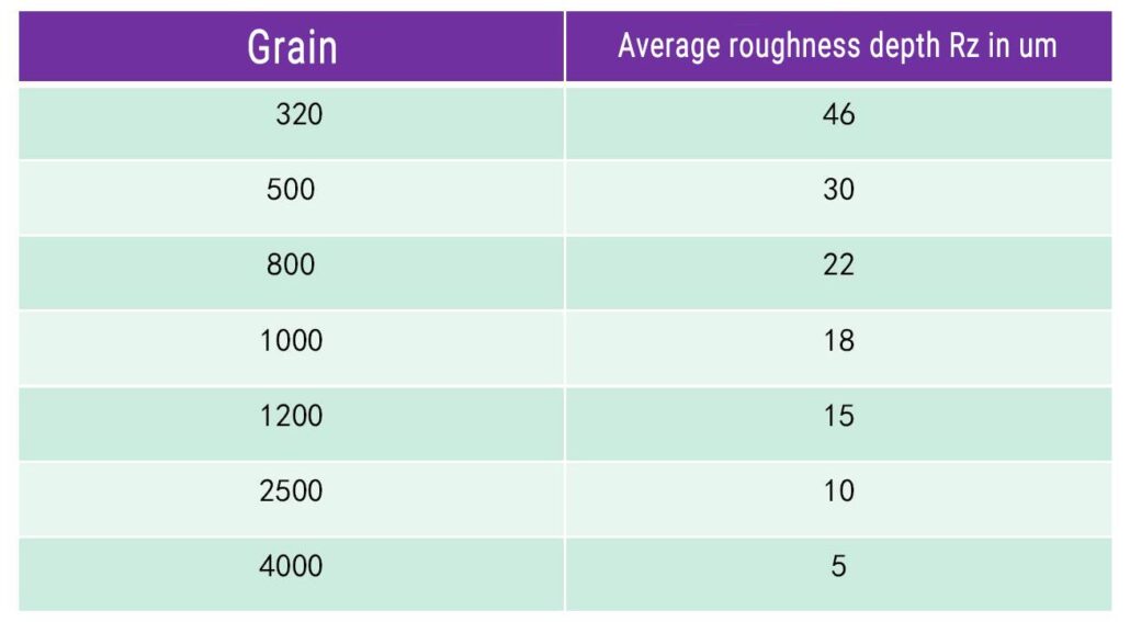
1) Rz
This involves evaluating the roughness of the surface, and the unit is μm. If the drawing does not define a specific value, then Rz=0μm is automatically applicable, which means that the metallographic specimen’s surface requirements (polished state) must be met.
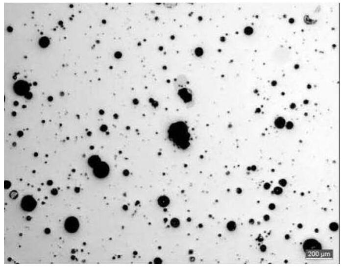
2) Porosity percentage(%)
This refers to the percentage of pores on the judged surface. If the requirement is less than 5%, then it must also be in the sub-judgment area of 3X4mm simultaneously.
Meet the requirements of less than 4% (this is consistent with the additional requirements of D1-D4 in VW50097). But when the drawings require that cast iron and cast steel porosity is less than 5%, the additional requirements of 4% can be found in the drawings marked in.
When 1%-4%, it is rounded to an integer. When it is greater than 5%, it is rounded by 5% as a series, and 0% does not exist.
3) Ф
This is the diameter of the hole**, the unit is mm, rounded by 0.5mm as a series, and it does not exist if it is less than 0.5mm.
4) A
It refers to the distance between pores (An in VW50097). This is a coefficient, the actual minimum distance allowed between two pores = diameter of the smaller one of the two pores X coefficient A
5) U
One can ignore pores whose diameter is less than U (corresponding to Pn in VW50097). Such a situation is only relevant for machined surfaces (such as sealing surfaces).
6) Z
The maximum number of individual pores allowed for machined surfaces only. Porosity is considered as a single pore and counted.
7) H, HR, Hk
Material packing (loose)!! Material packing refers to packing pores when the distance between two pores is smaller than the diameter of the smaller ones.
- H: Refers to the looseness of the entire evaluation surface
- HR: refers to the area of one-third of the wall thickness outside the entire evaluation surface
- HK: refers to the middle one-third of the whole judging surface
There are two options after H, HR, Hk
Option 0: Indicates that looseness is not allowed
Option 1: Indicates that looseness is allowed
If the drawing allows porosity and defines the maximum size of a single pore (Ф), then one should treat the porosity as a single pore. That is to say; the maximum porosity size cannot be greater than Ф.
8) N, NR, NK: Coarse pores group
Coarse pore populations are those pores when the material packing (loose) size is larger than the single maximum pore size (Ф) allowed.
- N: refers to the group of coarse pores on the entire evaluation surface
- NR: refers to the area of one-third of the wall thickness outside the entire evaluation surface
- NK: refers to the middle third of the whole evaluation surface
N, NR, Nk followed by two options
Option 0: Indicates that coarse pores are not allowed
Option 1: Indicates that coarse pores are allowed
If no indication of the latter option, then option 1 applies automatically, which means that coarse pores are allowed.
If the coarse pores are allowed to appear, then it means that the porosity is acceptable. Conversely, if the coarse pores are not allowed to appear, it does not mean that porosity is not allowed, as long as one meets the requirements for porosity (H, HR, Hk) of the drawings.
Example: VW50093- Rz0/%5/Ф3/N0
– VW50093 indicates the standard number used
– Rz0 surface roughness reaches a metallographically polished state
– %5 means the porosity is less than 5%.
– Ф3 means the largest single pore diameter is less than 3mm
– N0 means that coarse pores are not allowed
Example: VW50093- %10/Ф2/A3/H1
– VW50093 indicates the standard number used
– %10 means the porosity is less than 10%.
– Ф2 means the largest single pore diameter is less than 2mm
– A3 means the minimum distance between pores is 3xФmin
– H1 indicates that looseness is allowed for the entire evaluation surface.
Example: VW50093-Z4/Ф2/A2/Hk1/U0.5
– VW50093 indicates the standard number used
– Z4 means that there can be up to 4 pores on the judging surface
– Ф2 means the largest single pore diameter is less than 2mm
– A2 represents the minimum distance between pores 2X Фmin
– Hk1 indicates that looseness is allowed in the middle third of the judging surface
– U0.5 means one can ignore pores below Ф0.5
In some cases, the drawings do not indicate porosity requirements; then the following general requirements apply to the entire part:
– Cast iron or cast steel parts: VW50093-%1
– Zinc alloy parts: VW50093-%10
– Other parts: VW50093-%5
If there is an exceptional porosity requirement, it must be written into the drawing.
4.Determination of Porosity (PV6093)
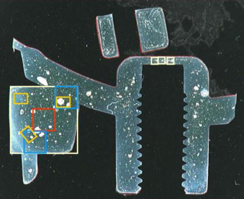
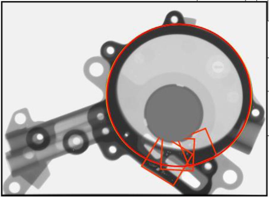
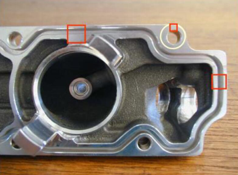
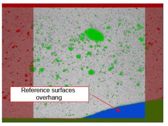
Selection of datum plane
Generally, only squares can be used (except for threads and surfaces with holes that do not have a sealing effect, in which case, one can select the entire section. If other reference surfaces are used, they must be approved by the development laboratory and added in drawings or related standards.
Key Points:
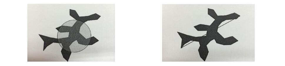
– The datum plane should be chosen so that it covers the largest possible area.
– The area of the part beyond the evaluation surface accounts for at most 5% of the evaluation surface area, and it should be excluded when the porosity is calculated by binarization
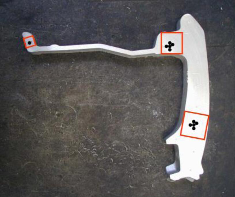
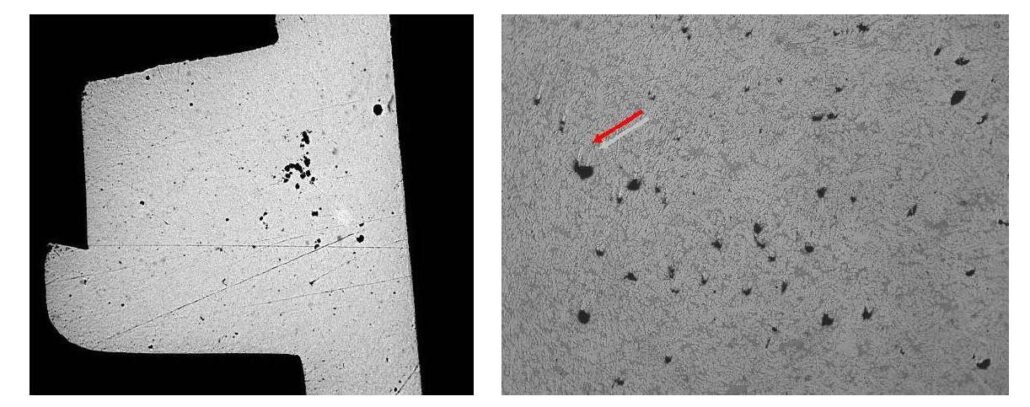
– The evaluation surface should try to select those areas that bear greater stress and have the risk of fracture. If the tester is not sure, it is necessary to communicate with the product designer.
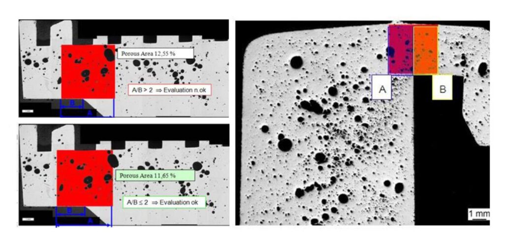
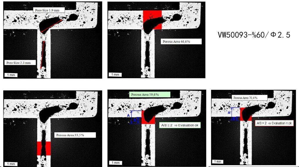
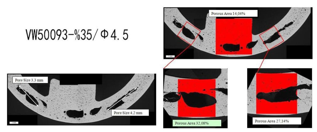
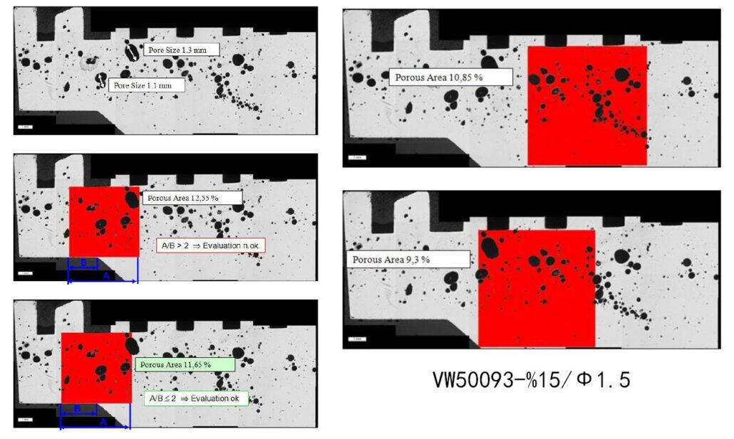
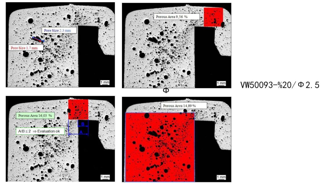
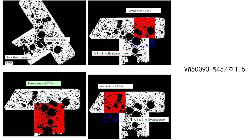
– If the judging surface may contain two different sized judging areas, the portion extending from the smaller area into the larger area shall not exceed half of the total area of the smaller area. In the figure, A/B should be less than 1.
Specimen Preparation Requirements
– Rz=0 The surface of the sample should be like a mirror surface. No scratches can be seen under the magnification of 100 times; the structure and boundary are clear.
There is no edge chamfering and relief, and there is no permanent plastic deformation.
– Rz>0 No obvious plastic deformation, avoid scratches and bruises, avoid overheating.
The corresponding approximate relationship between roughness depth as a function of the grain of the sandpaper is shown in the figure
Sample1
Sample2
Sample3
Sample4
Sample5