Brief Introduction Of Die Casting Mold Structure
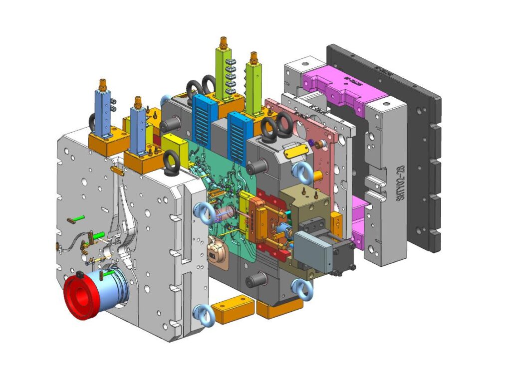
Die-casting mold is the main process equipment for die-casting production and the carrier of die-casting. Whether the production process can be carried out smoothly and whether the casting quality is guaranteed depends largely on the rationality of the mold structure.
The correct use of the die-casting process plan and various process parameters in the die-casting production is the decisive factor for obtaining high-quality castings, and the die-casting mold is the specific embodiment of the process plan and the basis for the selection and adjustment of process parameters.
1.Basic Mechanism Of Die Casting Mold
The die-casting mold is composed of two main parts: fixed mold and moving mold. The fixed die is fixed on the fixed plate on one side of the die-casting machine chamber, which is the side where the molten metal begins to enter the die cavity of the die-casting die. The fixed mold is also part of the mold cavity. There is a sprue on the fixed die that is directly connected to the pressure chamber or nozzle of the die casting machine.
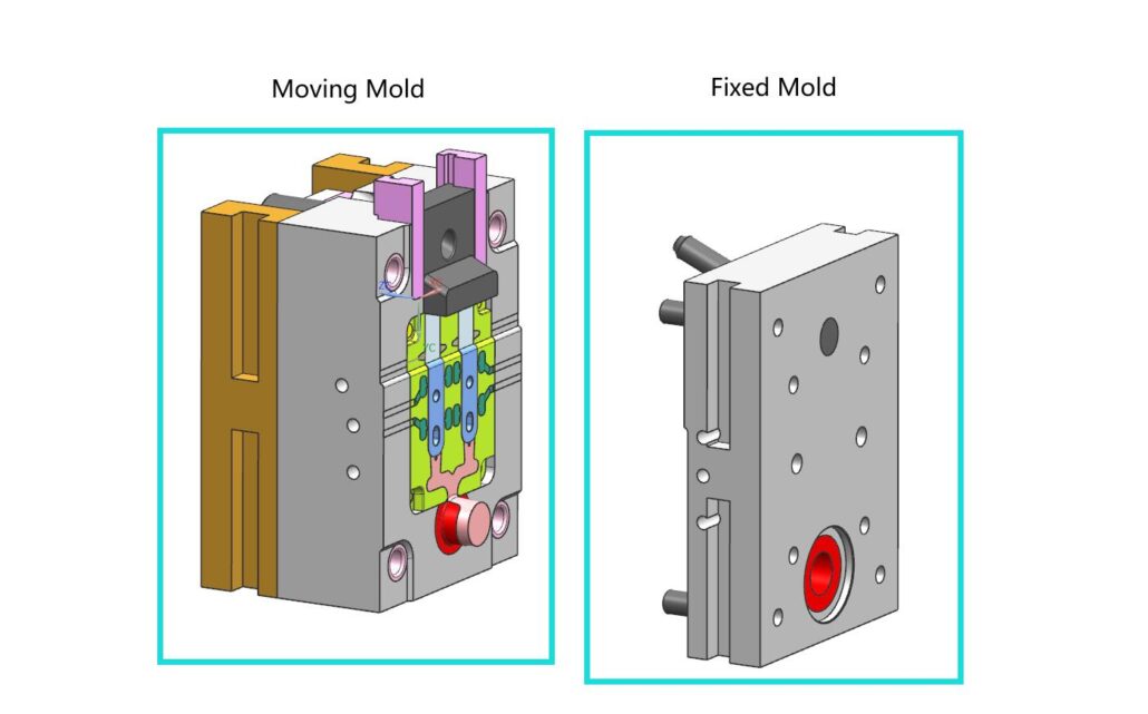
The movable mold is fixed on the moving plate of the die-casting machine and moves with the movable mold seat to separate and close the fixed mold. It is for the mold that needs a slide core mechanism, the core pulling, and casting ejection. The mechanism is usually also provided on the movable die side.
The basic mechanism of the die-casting mold is shown in the figure:
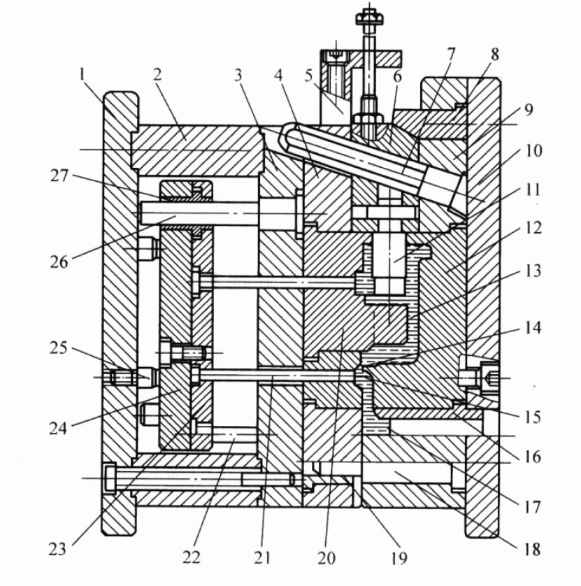
1)Moving clamping plate: the plate that fixes the moving mold on the die-casting motorized mold base.
2)Space block: It adjusts the closed height of the mold and forms a block-like part for the space position required by the ejection mechanism.
3)Moving die support plate (support plate): a plate that prevents axial displacement of parts such as moving die inserts, cores, guideposts, or guide sleeves and withstands molding pressure.
4)Moving die: a plate used to fix the moving die insert, core, guidepost, or guide sleeve and to enhance the strength and rigidity of the insert.
5)Core-pulling limit stop (stop block): a block-shaped part that limits the final position of the slider after being pulled out.
6)Core-pulling slider (slide):a part that can slide along the guide structure to drive the movable core or insert to complete the extraction and reset action.
7)Angle pin: a cylindrical part that is inclined to the parting surface and causes the slider to slide in the mold as the mold opens and closes.
8)Wedge block: It is a part with an angle that locks the slider when the mold is closed.
9)Fixed die: a plate that fixes the fixed die insert, core, guidepost, or guide sleeve and enhances the strength and rigidity of the insert
10)Fixed clamping plate: a plate that fixes the fixed die on the die-casting machine’s fixed die base
11)Side core: The core that realizes displacement with the help of the core-pulling mechanism and completes the extraction and reset actions.
12)Fixed die insert: It is fixed in the fixed die sleeve and forms the main part of the mold cavity.
13)Cavity: After the mold is closed, it is used to fill the molten metal and form the casting
14)Inner gate: the channel and entrance for the molten metal to enter the mold cavity
15)Runner:a passage from the end of the sprue of the mold gating system to the inner gate
16)Sprue bush: a circular bush-like part that forms a sprue
17)Sprue: a passage from the entrance of the mold gating system to the runner
18)Guide pin: It is a cylindrical part that cooperates with the guide sleeve installed on the other half of the mold to determine the movable and fixed molds’ relative position and ensure the accuracy of motion guidance.
19)Guide bush(guide bush): it is a round sleeve-shaped part that cooperates with the guidepost.
20)Moving die insert: It is fixed in the moving die sleeve and forms the main part of the mold cavity
21)Ejector pin: a rod used to push out a casting or gating system
22)Return pin: A rod that resets the ejection mechanism by means of the closing action of the mold.
23)Ejector pin retaining plate: a plate used to fix the push-out and reset parts, clamp and fix the ejector pin retaining plate, and other parts.
24)Ejector plate: a plate that supports the ejector reset parts and transmits the ejector force of the die-casting machine
25)Stop pin: a part used to support and limit the reset position of the push-out mechanism
26)Ejector guide pin(ejector guide pin): Cooperate with the ejector guide sleeve, used to push out the cylindrical guide parts in the mechanism
27)Ejector guide bush: a round sleeve-shaped part that cooperates with the ejector guidepost
A set of mold usually contains the following parts of the unit structure:
A.Molding part:
After the fixed mold and the movable mold are closed, a cavity forming the shape of the casting is formed, which becomes a cavity. The structure of the press casting is different, and the cavity can be all set in the fixed mold or the movable mold, or the fixed mold and the movable mold each occupy a part.
The parts that make up the cavity are called formed parts. Formed parts include fixed and movable inserts and cores. In addition, the gating system and the drain system are also part of the cavity.
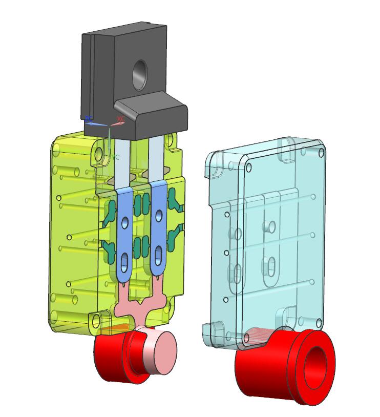
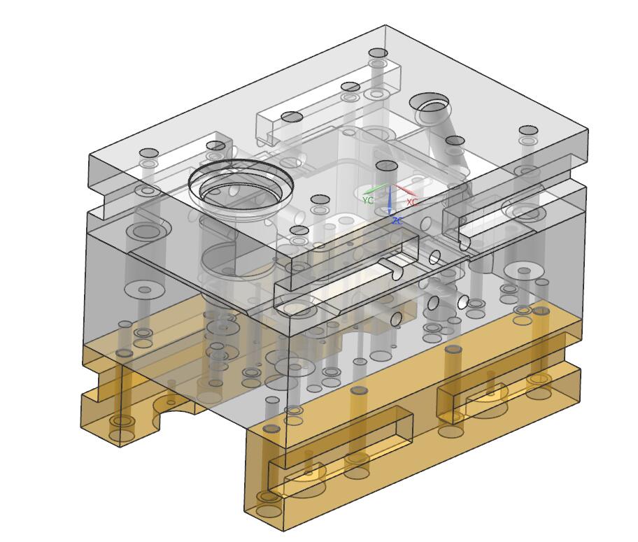
B.Mold base
This includes various templates, mold bases, and other structural parts. The function is to combine and fix the various parts of the mold according to certain rules and positions and enable the mold to be installed on the die-casting machine.
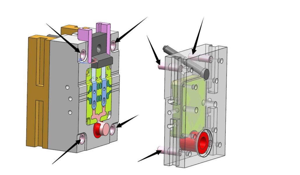
C.Guide parts
Guide parts whose function is to guide the closing or separation of the movable mold and the fixed mold and ensure the accuracy requirements of the mold opening and closing.
D.Eject system
This is the mechanism that pushes the casting out of the mold, including the ejection and reset parts and the guide and positioning parts of the mechanism itself. The important and easily damaged pushrods should be made of the same material as the molded parts.

E.Gating system
It is the channel connecting the cavity with the pressure chamber or nozzle, which guides the molten metal to enter the mold cavity in the specified direction. It also influences the pressure and speed of the molten metal entering the forming part. Dao and other components.

F.Overflow system
This refers to the exhaust trough and overflow trough system. The exhaust groove is a channel to remove the gas in the pressure chamber, runner, and cavity, and the overflow groove is a small cavity for storing cold metal and paint embers. In addition, a vent plug is set in the deep cavity of the fuselage to improve the exhaust conditions there.
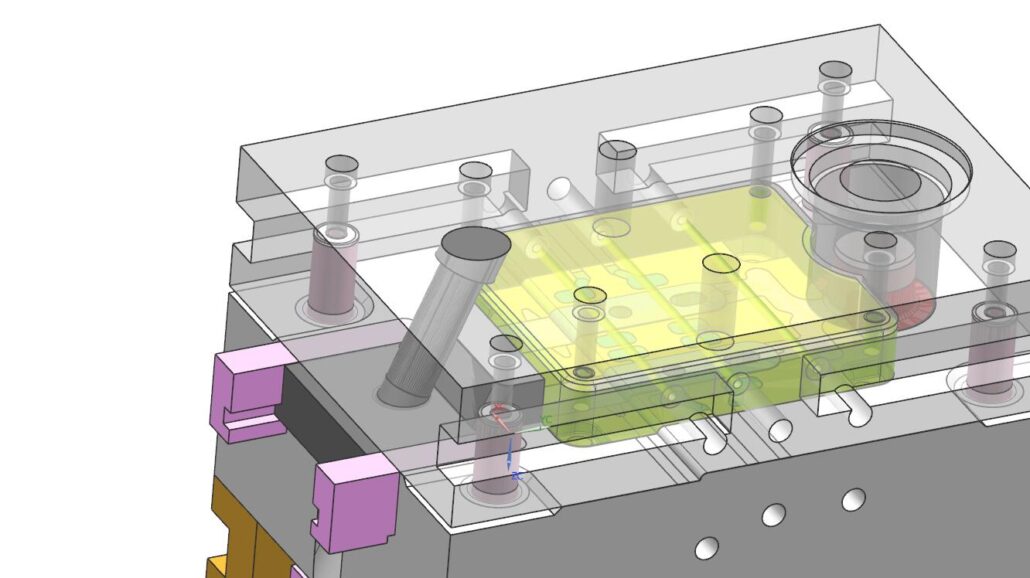
G.Core pulling mechanism
For some castings, when the core pulling direction is inconsistent with the opening and closing direction, it is also necessary to set a core pulling mechanism on the mold to remove the casting from the mold. Show. The core-pulling mechanism is also a very important structural unit in the die-casting mold, and its forms are various.
H.Cooling-heating device
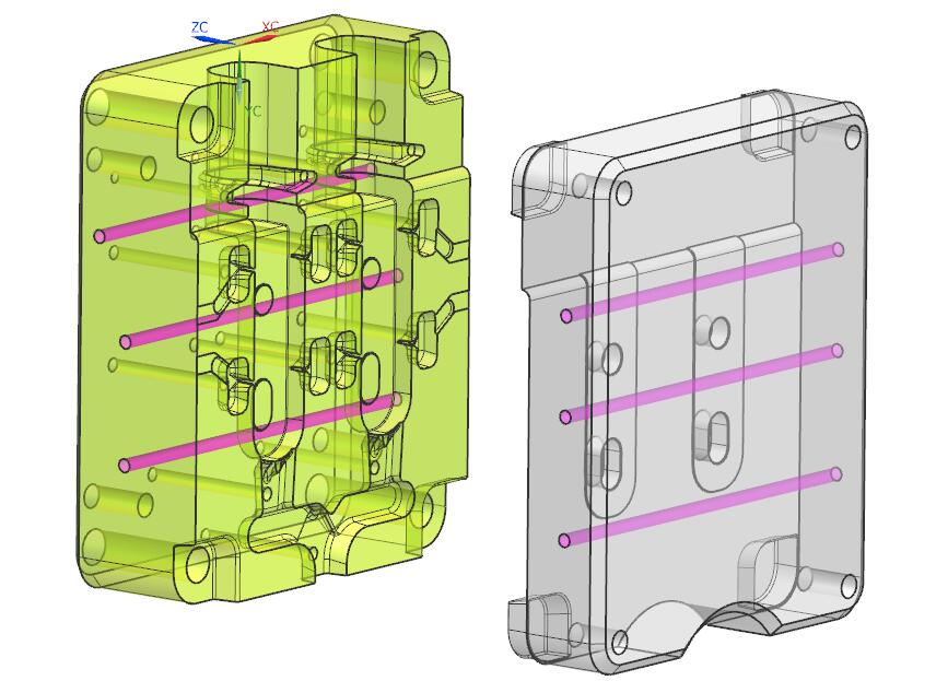
In order to keep the distribution of the mold temperature field in line with the needs of the process, sometimes a cooling device or a cooling-heating device should be set in the mold, which is especially important for scientifically controlling process parameters and ensuring the quality of castings. The life of a mold with a good cooling (or cooling-heating) system can be greatly extended.
I.Other
Other parts include bolts for connecting and fixing each structural unit, positioning, guide pins, etc.
2.Structure Example of Die Casting Mold
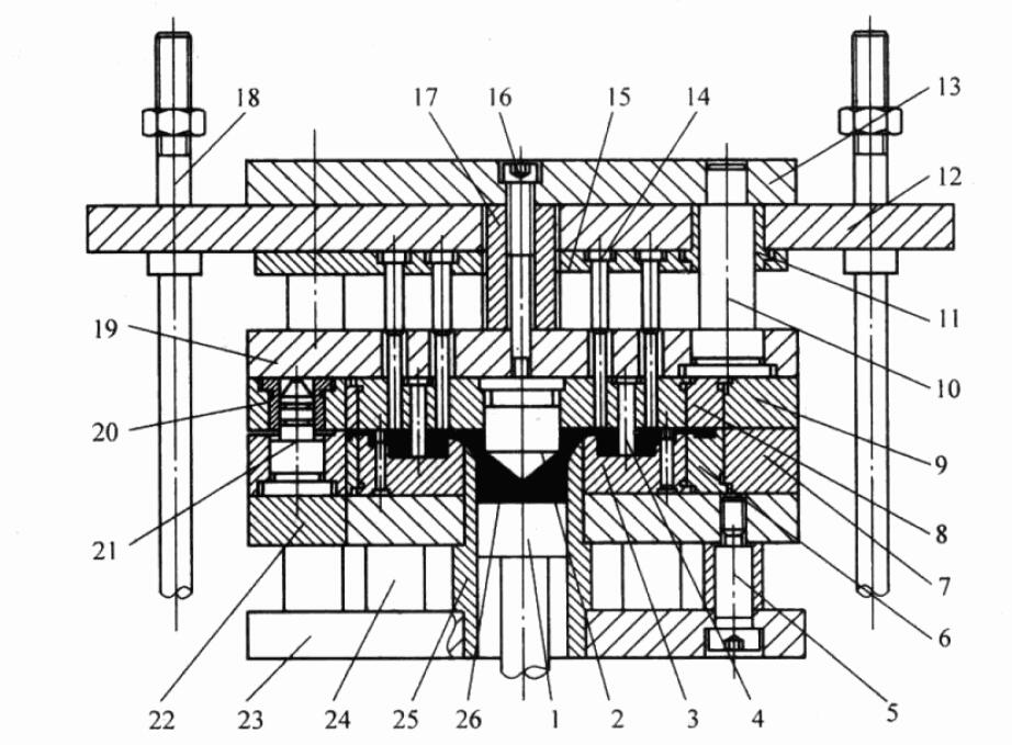
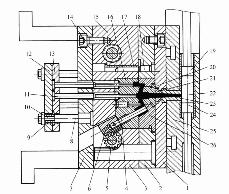
The basic structure of the hot chamber die casting mold is shown in the figure.

The inner shape of the sprue sleeve 11 of this kind of mold sprue is conical, and the diverter cone 12 is arranged on the movable die insert, the function of which is to facilitate the sprue to escape from the fixed die;
The wrapping force of the cone is relatively large, and a push rod 17 must be placed next to the shunt cone so that the sprue can be pushed out synchronously when the casting is pushed out. The ball socket on the right end face of the sprue sleeve 11 is matched with the spherical surface of the die-casting machine nozzle, and its radius size should be paid attention to when designing.
The sprue sleeve can be located in the center of the mold, or it can deviate from the center within a certain range, but the maximum distance that the die-casting machine allows the center of the sprue sleeve to deviate from the center of the mold is certain, and attention should be paid to the selection within this range during design.
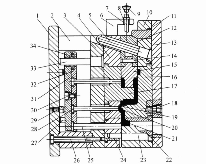
The structure of the vertical cold chamber die-casting mold is shown in the figure.
The inner shape of the sprue sleeve 20 of such a mold sprue is also tapered, and sprue sleeves with different diameters can be replaced as needed. Usually, the gate sleeve of the vertical cold chamber die casting machine is in the center of the mold and cannot be changed, so it is suitable for the mold with the center gate.
The basic structure of the eccentric gate die casting mold of the horizontal cold chamber die casting machine is shown in the figure.
For horizontal cold chamber die casting machines, which is the most commonly used mold structure, the sprue is located below the cavity to ensure that the molten metal does not flow into the cavity before injection.
The basic structure of the horizontal cold chamber die casting machine using the center gate die casting mold is shown in the figure.
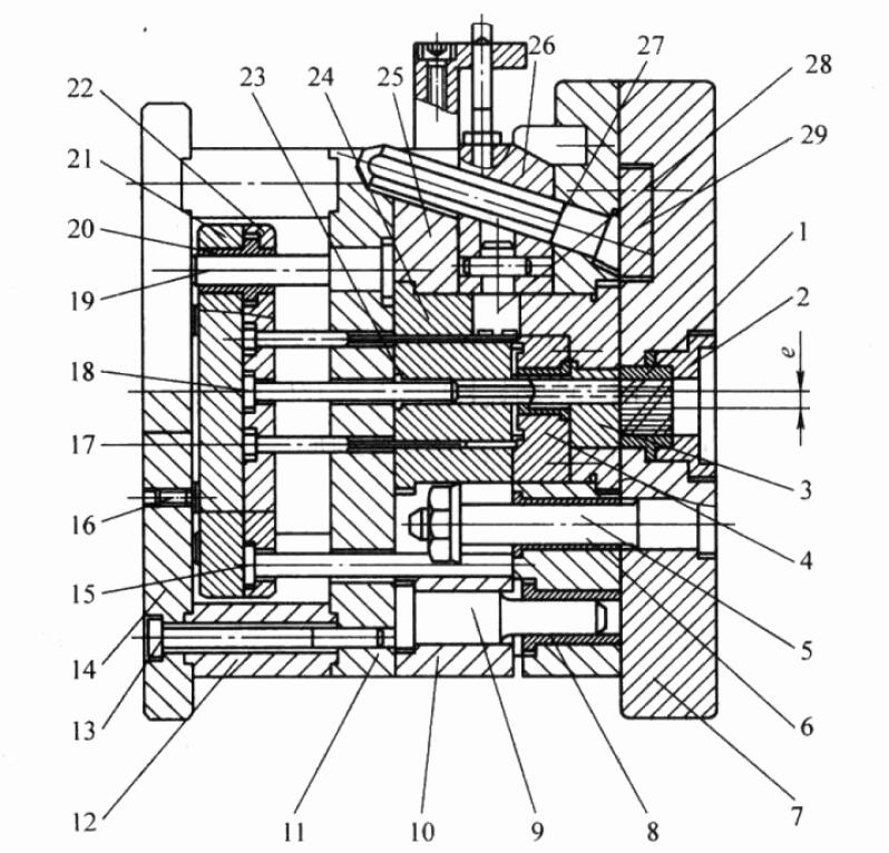
When using this mold, the center gate should be set above the pressure chamber to prevent the molten metal from flowing into the cavity by itself. This is achieved by the two parts 2 and 3 in the figure, which will make it impossible to take out the remaining material in the pressure chamber.
For this purpose, the sleeve plate and insert of the fixed mold are made into a structure that can slide along the guide rod 5, and the sprue sleeve 2 is made of the internal thread. When the mold is opened, the injection punch moves with the fixed and movable molds to push out the remaining material.
At the same time, the remaining material is forcibly rotated by the internal thread of the gate sleeve and cut off by the root. After cutting, the sliding part of the fixed mold is blocked by the end of the guide rod, the movable mold continues to move, and the mold is opened to push out the casting.
The mold structure of the full vertical die casting machine is shown in the figure.
