
Casting Evaluation - Hole
Die casting remains a big but yet vital concept. It involves several technicalities which are quite simple with the right explanations. This article will focus on all you need to help in the evaluation of die casting holes.
Let’s start.
1.Design Form of Casting Hole
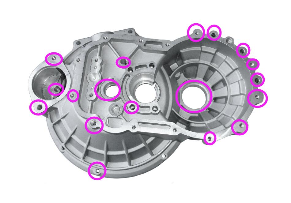
The hole on the die casting is an indispensable element. The form of the hole can vary and can be roughly divided into the following categories:
Round hole
A. This includes round holes with assembly functions, which are usually threaded holes. It also features self-tapping threaded bottom holes and via holes, etc.
B. Positioning holes: used for the subsequent processing and assembly of castings, which can be through holes or blind holes
Square hole
A. Positioning hole: the hole that matches the die casting assembly
B. Function holes: holes that realize a certain function, such as threading holes, heat dissipation holes, etc.
Special-shaped hole
A. Functional use: this includes threading holes, oil holes, air holes, etc.
B. Weight-reducing hole: do not let the local wall thickness of the casting be too thick, and reduce the hole used for the material. Moreover, the wall thickness of the castings can be kept consistent, better fluidity can be obtained, mold maintenance can be reduced, and mold life can be prolonged.
2.Hole Manufacturing Method
There are different ways to manufacture the die casting holes. Each method has its uniqueness and model. They include:
- Direct die-casting forming;
- Pre-cast bottom hole + Finishing
- Relying entirely on processing
Direct Die Casting Hole
The direct die-casting hole is restricted. This is because, during the die-casting process, the molten metal will shrink toward the center of the mold shape when it solidifies. As a result, it will generate a tightening force on the core of the hole, and at the same time, it will also generate a bending force on the core. In all, it increases the chances of the core Break off.
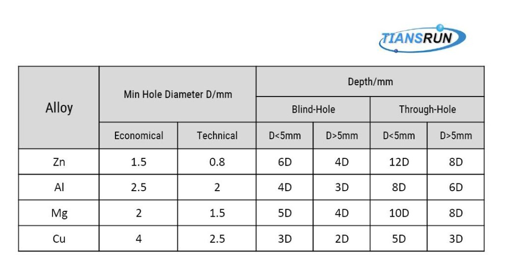
Therefore, the die casting process has size restrictions on the diameter and depth of the hole.
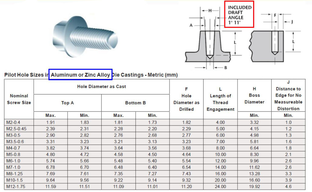
Aluminum alloy with a minimum aperture of 2.5mm is very safe and reliable, and sometimes 2mm is also possible. When we evaluate the hole, the most important thing to pay attention to is the relationship between the hole diameter and the hole depth. Too deep a hole will directly affect the life of the mold pin.
Pre-cast bottom hole + Finishing
Before we proceed, it’s best to ask what a pre-cast hole means?
It is difficult to cast some holes completely, but we can cast part of the bottom hole, and we call that a pre-cast hole.
Compared with fully machined holes, the advantages of pre-cast holes are:
- It reduces the use of materials
- It reduces machining and the possibility of hole exposure
- It can be used as a positioning function for machining.
In addition, the requirements for the position of the holes on the product are relatively high, and the die-casting process cannot guarantee that the position accuracy of the casting holes meets the requirements. In this case, pre-cast holes can be made first and then machined to meet the requirements.
Before deciding whether the holes on the product should be made into pre-cast holes, it is necessary to do a rationality review such as;
- Precision requirements for holes
- The structure of the product, the location of the hole, and the thickness of the surrounding casting
- Whether the die-casting process can meet the requirements, such as cooling time, mold opening time, etc
Fully Machined: Cut Hole
A. When the hole diameter on the product is too small, die-casting is generally not used for direct forming. Instead, the cutting method is used, which is more economical and reasonable.
B. For the holes on the product, if the position requirements are very high, and the die-cast holes or pre-cast holes cannot be used to ensure accuracy, then the holes need to be processed directly.
3.Threaded hole
The threaded hole on the die-casting part is usually not directly formed by die-casting, but a threaded bottom hole is produced by die-casting, and then the threaded hole is processed twice.
The machining allowance of the threaded bottom hole should not be too large. Excessive machining allowance will cause porosity in the casting. Sometimes if there are pores, you can try to machine the threads with an extrusion tap to improve the pore problem.
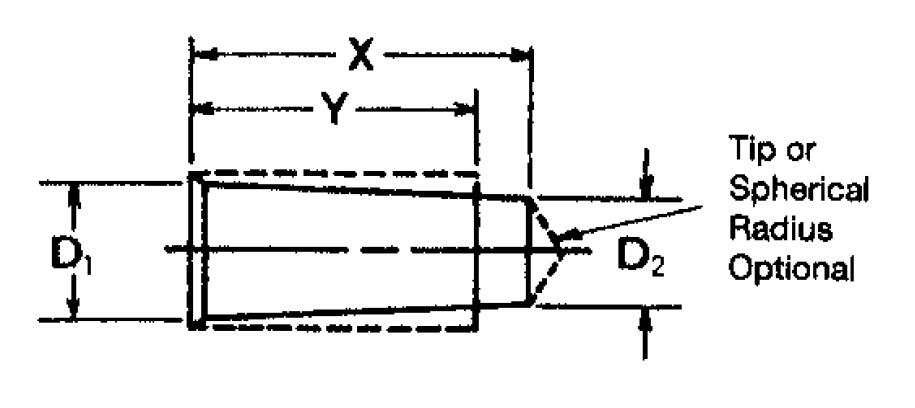
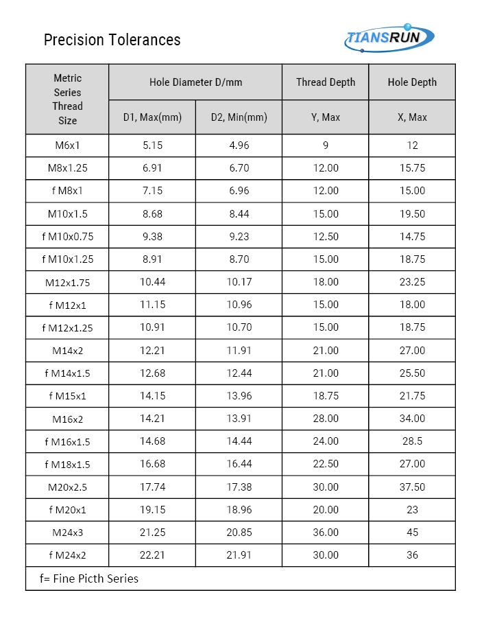
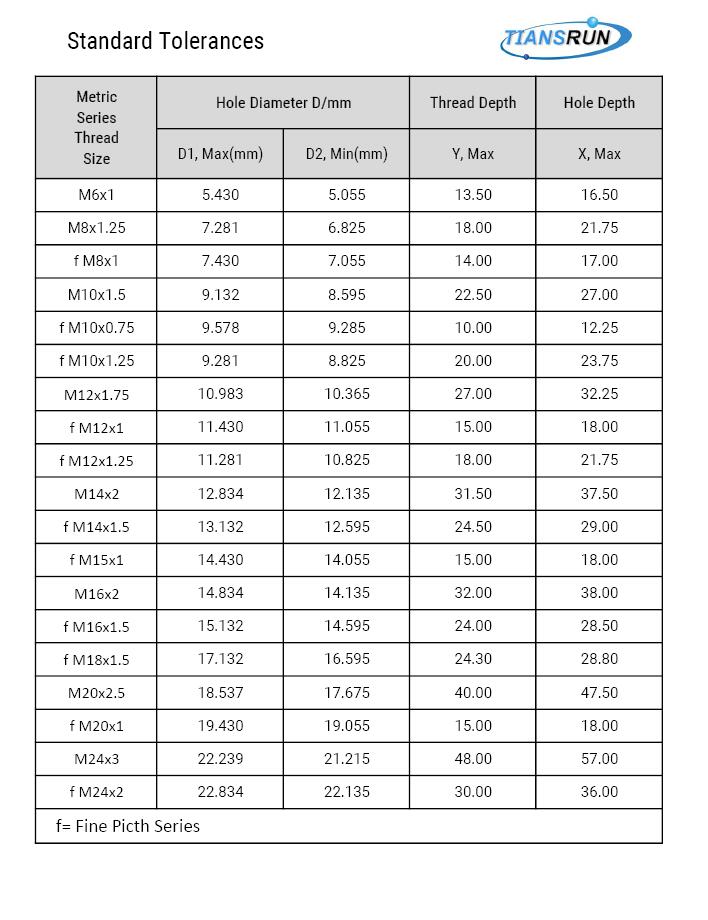
The figure shows the relationship between the casting threaded bottom hole and the depth, divided into a standard level and precision level
Recently there has been a newly developed self-tapping threaded hole. The threaded bottom hole is formed by die-casting, and then a special screw is used to realize the function of fastening the product directly.
The aluminum alloy self-tapping screw uses a triangular tooth screw with a triangular lead-in end. This helps to reduce the resistance of the screw when it penetrates the connected object. It also helps prevent the screw from loosening in a vibration environment.
Since no nut is required, the triangular thread self-tapping and self-locking screw helps users reduce the cost of use.
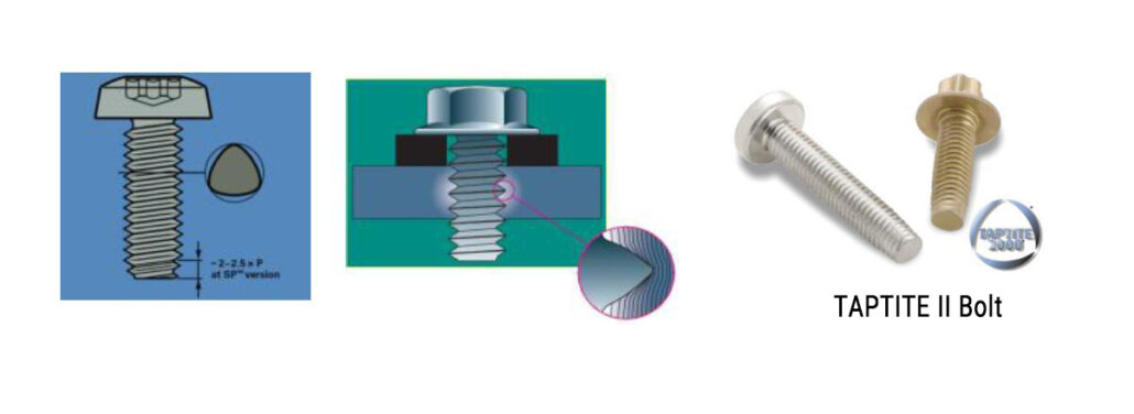
The size relationship of self-tapping thread reserved holes is shown in the figure below
4.Mold Pin Fracture Mechanism
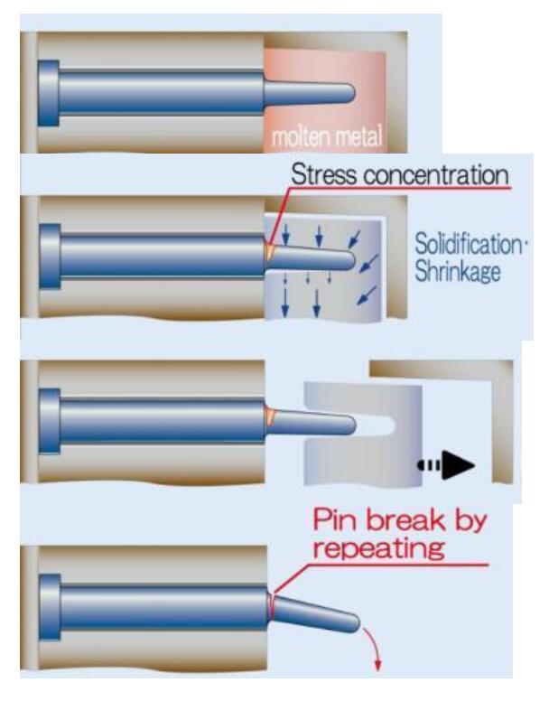
Pins usually form the holes in the die-casting parts in the mold. Below we analyze the mechanism of pin fracture:
- After molten metal fills the entire cavity, the pin is in a high temperature and high-pressure environment;
- When the molten metal solidifies and shrinks, it produces a great packing force on the pin. At the same time, the entire casting shrinks in the direction of the center, which produces a large shrinking force on the pin;
- When the die-casting part is demolded, the pin bears mechanical tension;
- In the continuous production cycle, the slender pin is broken or bent under the alternate action of packing force, contraction force, and tensile force.
5.Optimized Design of hole and pin
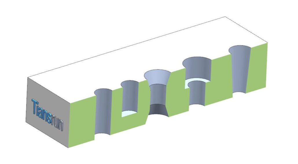
The Design of the pin determines its life to a large extent.
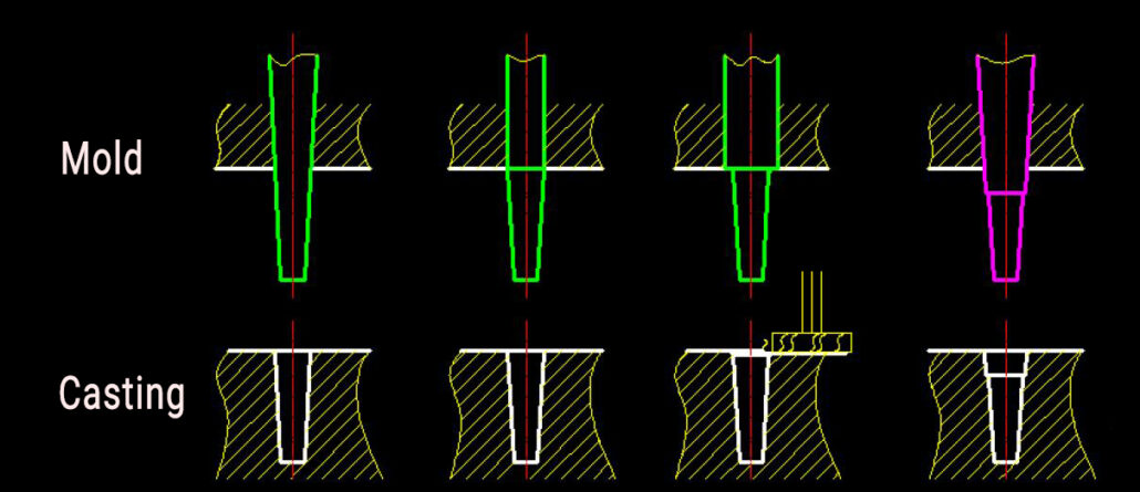
The figure shows that the upper part is the mold and pin, and the lower part is the hole corresponding to the casting. Here are four different shapes of pins.
- All have the shape of draft angle; this kind of pin is not easy to break;
- The front end has a draft angle, and the back end is straight, which is easier to break
- The back end is larger than the front end, which is also easier to break;
- The front end is made into a stepped type, which has higher strength at the bottom of the pin. This one has the longest lifespan.
Therefore, when we evaluate the Design of the hole, we try to extend the service life of the mold as far as possible and make the product more economical.
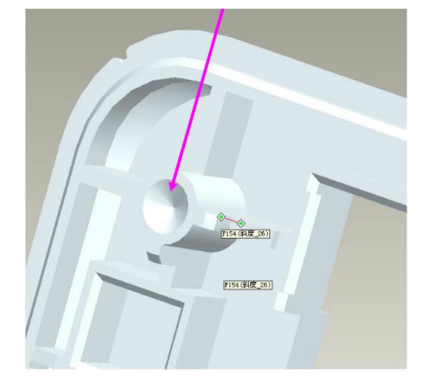
For forming holes with too deep depth, different forming methods can be selected to increase the strength and life of the pin.
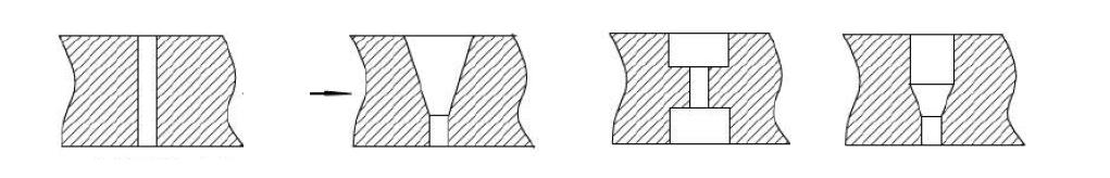
The original shape has only one through-hole, and the mold pin will be relatively slender and easy to break. Then it can be designed to have pins on both sides to complete the molding of a hole.
6.Optimized Design Case
Case one
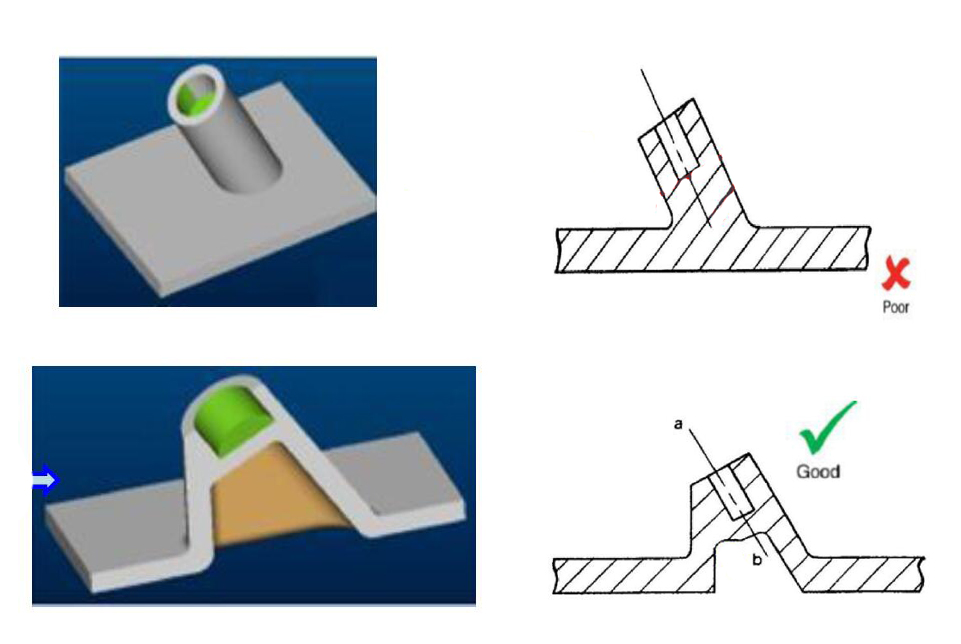
Problems in the initial design:
- The mold forms an upside-down structure and cannot be formed;
- The local wall thickness of the casting is too thick
Improvement: By designing the material/reducing special-shaped hole, the structure of the undercut is avoided, and the wall thickness is made uniform.
Case two
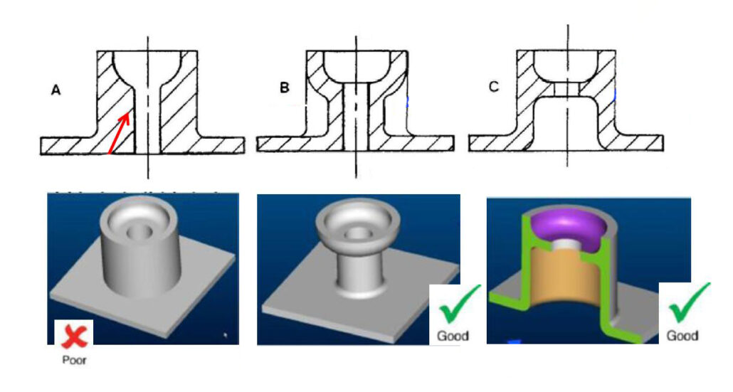
Problems with initial design A:
If the local wall thickness of the die casting is too thick, there will be shrinkage defects in the casting.
Option B: After the casting is optimized, the wall thickness is evenly distributed, the molding is easier, and there is no internal shrinkage defect. But the mold needs a side slider structure.
Solution C: The casting structure is simple, the wall thickness is uniform, and the mold structure is simpler and more reliable.