
Die Casting Die Life and Failure Mode
It’s a normal phenomenon for customers to ask vital questions. Usually, many customers will ask us,
- How many times can our molds be punched?
- You said that the life of the mold could reach 50,000 molds and 100,000 molds. Why doesn’t my mold reach this lifespan?
- Does it mean that my mold cannot be used after 100,000 molds?
- How to maximize the life of our molds?
The questions keep coming, and honestly, they all deserve an answer. So in a bid to achieve this feat, we will discuss the concept of mold life.
1.Die Casting Mold Life
The mold life is the maximum number of products that the mold can form under the condition of ensuring the output of qualified die castings. Including repeated mold repair, and replacement of wearing parts, until the main part of the mold (mainly refers to the mold core) needs to be replaced, the total number of qualified parts that the mold can produce.
Mold life is not an absolute value but a relative concept. Assuming that the same mold produces the same product, the mold may reach the design life in advance if the testing standards are very strict. On the other hand, if the inspection standard is relatively loose, the mold can be produced appropriately for a longer time.
Another example; if the surface requirements are not very high, a little crack is acceptable, then the mold life is relatively high. However, another product has high surface requirements. Under similar cracking conditions, the product does not meet the quality requirements, so the life of the mold has expired.
2.Failure of the Mold
The failure of the mold is divided into two cases: Normal failure and Abnormal failure
- Normal failure refers to the slow plastic deformation of the mold or relatively uniform wear and fatigue fracture after the mold is used in mass production and cannot be used continuously
- Abnormal failure means that the mold has not reached the expected life due to mold quality problems or improper die-casting production operations, resulting in early failure of the mold.
3.Several Forms of Mold Failure
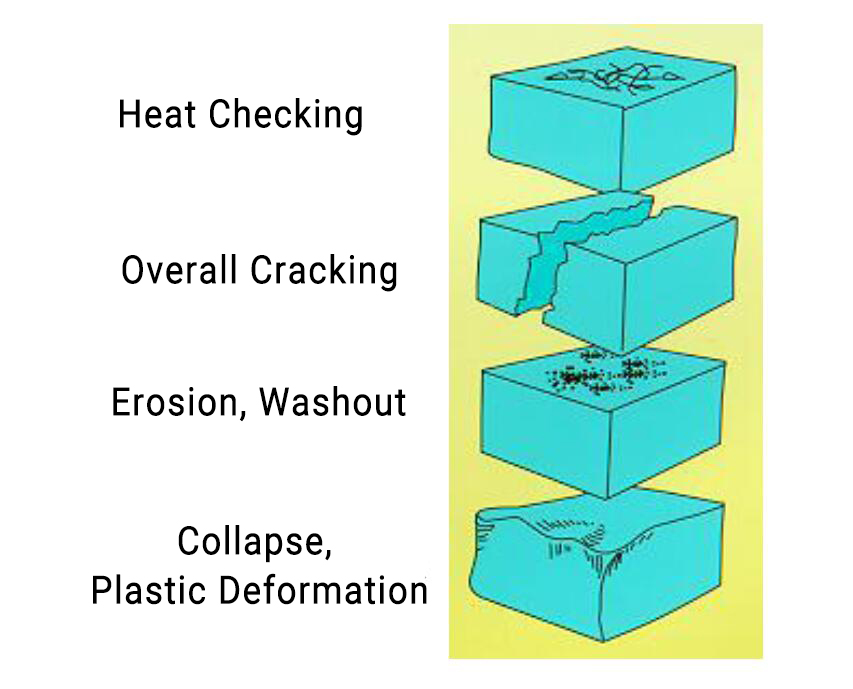
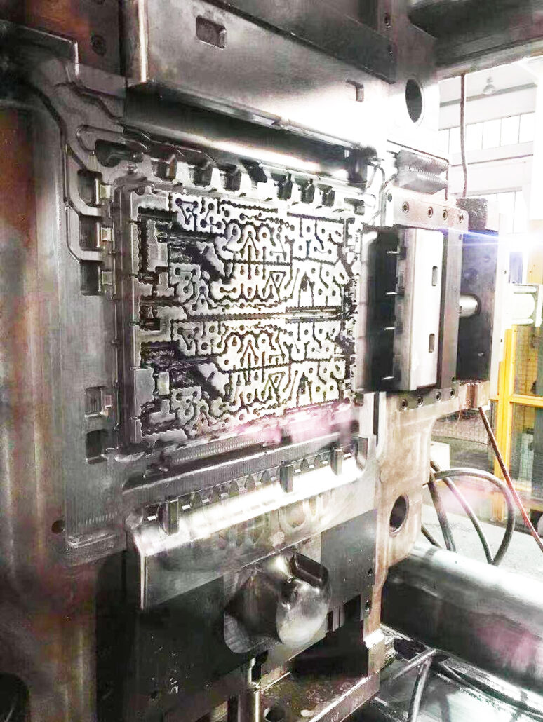
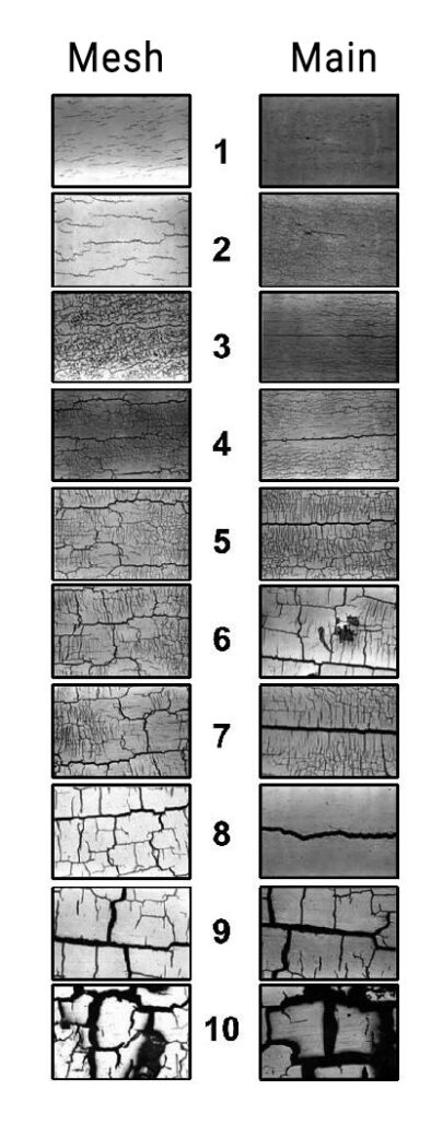
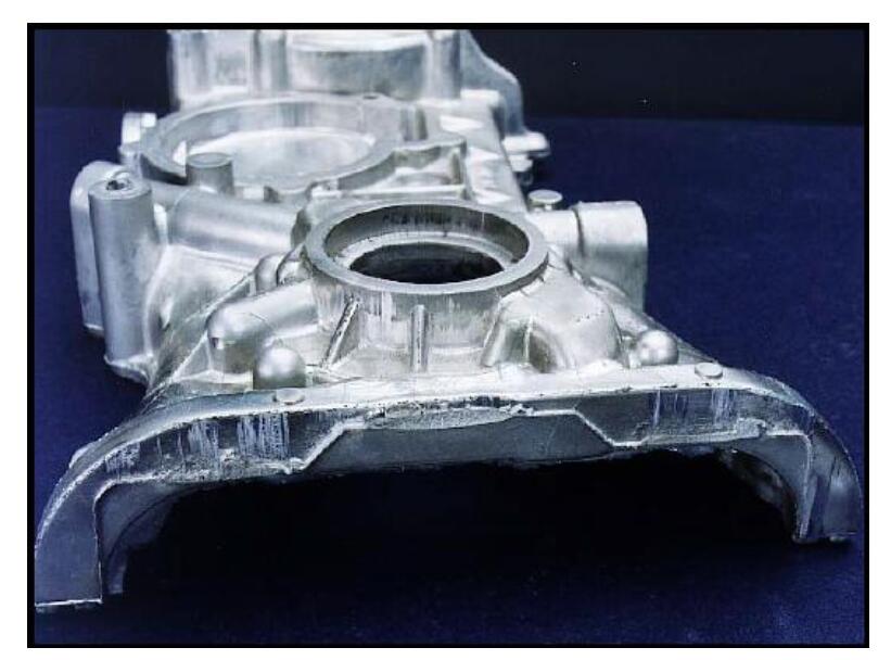
Heat checking and overall cracking
After the mold is used for a period of time, strip or mesh cracks will appear on the surface of the workpiece. This is because, during the mold’s production process, the mold’s surface is repeatedly scoured by the molten metal, the temperature difference between the mold surface is large, and the compressive stress and the tensile stress appear alternately. As a result, thermal fatigue cracks occur over time.
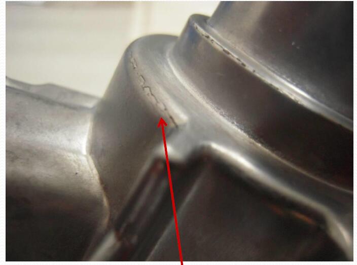
Hot cracks will roughen the product’s surface, increase the mold release resistance, and cause the product to be pulled or deformed. If the hot crack develops further, it will eventually lead to the overall cracking of the mold.
Criteria for hot cracks: mesh cracks and main cracks.
In the mechanism of hot crack formation, the most important factor is the temperature cycle of the mold surface. If the temperature of the mold is low, the temperature difference in the die-casting process is small, and the time at high temperature is short, which can effectively slow down the occurrence of hot cracks.
For hot cracks that appear in the early stage, it is usually necessary to review the quality of mold materials, whether there are problems in mold design, whether there are problems with heat treatment and surface treatment of molds, and whether the parameters of die-casting production are reasonable.
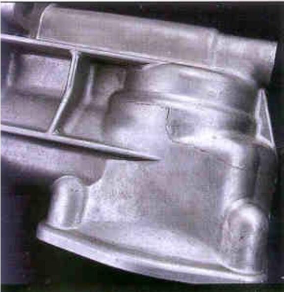
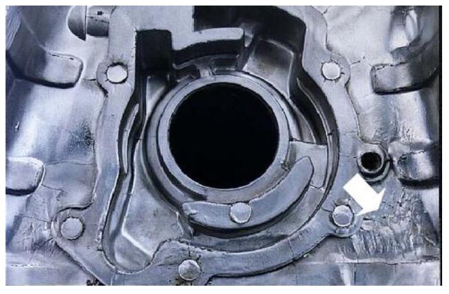
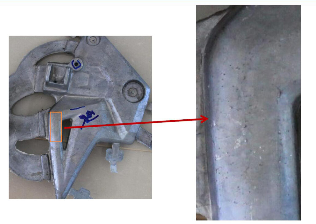
Washout
Washout is most common near the inner gate or cores that are directly scoured by molten aluminum. Washout can roughen the surface of the die casting. It is easy to stick to the mold if it is in the demolding direction.
A few common causes of washout are:
- The filling speed of the molten metal is too fast. When the filling speed of the aluminum alloy is greater than 55m/s, the washout will be significantly increased
- The higher the molten metal temperature, the more prone it is to washout.
- The high-temperature hardness of the mold material is low, and washout is easy to occur.
- The surface of the mold is not well treated, and it is also prone to washout.
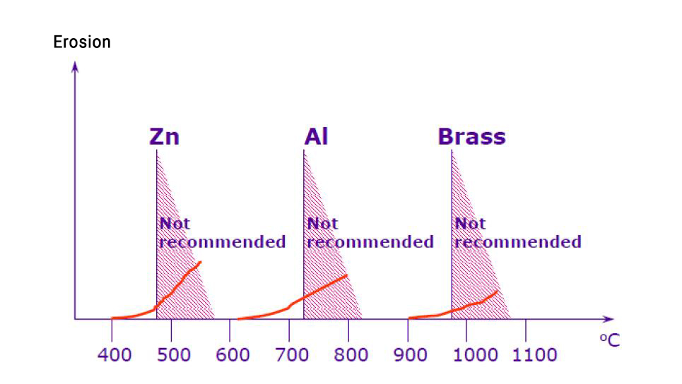
Erosion and sticking
Erosion is the chemical reaction of the molten metal with the mold material. The lack of a protective layer on the surface of the mold cavity allows molten metal to penetrate into the mold surface. At the same time, the iron element in the mold will diffuse from the mold surface into the die-cast metal.
Therefore, an intermetallic compound is produced between the mold surface and the die-cast metal. In short, aluminum and iron react to produce aluminum-iron compounds. Therefore, the aluminum alloy contains an appropriate amount of iron, which can effectively reduce erosion.
Adhesion
The main reasons for erosion and adhesion are as follows:
- The temperature of the die-casting molten metal is too high;
- Composition of die-cast metal: 0.8% iron and 0.5% manganese are added to reduce erosion and stick effectively
- Filling speed of die-cast metal
- Surface treatment of molds
Erosion and adhesion are a function of metal velocity
Mold deformation (collapse, plastic deformation)
This is as a result of the following;
- The mold design is too small, and the wall thickness is too thin, resulting in poor mold strength and deformation
- The collapse of the parting surface or cavity is caused by the high-temperature strength of the mold material being too low.
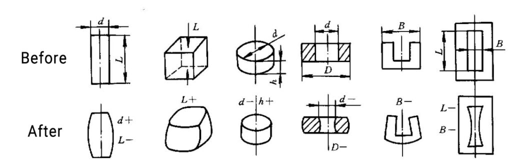
When mold deformation occurs, it results in the following
- It makes the length of the shaft-shaped mold shrink and the diameter thicker
- The diameter of the disc-shaped mold shrinks, and the thickness increases
- It makes the outer diameter and inner hole of the annular mold shrink and increase the thickness
- The corners of the cube-shaped mold are contracted, and the planes are raised.
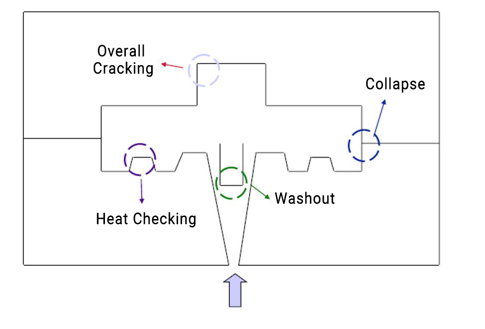
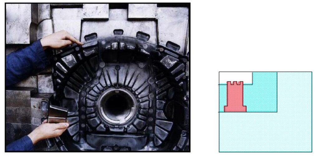
The failure modes that are prone to occur in different parts of the die-casting mold are shown in the figure
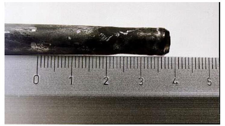
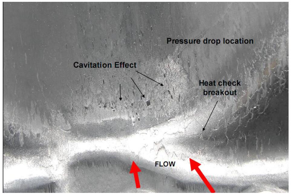
Cavitation
Cavitation is mainly formed by the implosion of bubbles in molten metal under pressure. When the pressure at the local position in the casting is lower than the saturated vapor pressure, cavitation occurs. The implosion’s high impact energy and heat cause the material to collapse on the mold surface.
Areas that are prone to appear:
- It is easy to appear in the position where the flow direction of the molten metal suddenly changes
- Prone to flow obstructions, where pressure fluctuations occur
The surrounding metal flow will be disrupted at the location where cavitation occurs, resulting in low vapor pressure, resulting in more cavitation, which continues to deteriorate.
4.How to Improve Mold life
There are many factors that affect the life of die-casting molds, which need to be considered comprehensively. The systematic thinking ranges from die-casting part design, mold design, and manufacturing to the final die-casting production link. Only by controlling every link can we maximize the service life of the mold.
Through the following measures, we can improve the life of die casting molds:
4.1 Die casting structure
Reasonable wall thickness
Considering the thermal load, the design of the die casting should be thinner. Generally, the suitable wall thickness is 3mm to 6mm. Of course, the fluidity and strength of castings should also be considered comprehensively.
Uniform wall thickness
Prevent thermal junction, resulting in local thermal cracking. Die-casting parts should be as uniform as possible in wall thickness. If the wall thickness is too thick, hot junctions will be formed, resulting in local thermal cracking and affecting the life of the die-casting mold.
4.2 Selection of mold materials
Common mold steels include H13, SKD61, 8407, 2344, and so on. Select the appropriate steel according to the requirements of the product. Good steel can withstand higher thermal fatigue. Steel impurities are also less.
4.3 The mold must have sufficient strength, and the wall thickness of the mold must be sufficient.
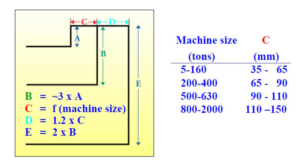
Check out the following parameters;
- Cavity depth to mold thickness ratio less than 1:3
- The distance between the cavity surface and the cooling water channel is greater than 25mm
- The distance between the cavity at the right angle and the cooling water channel is greater than 50mm
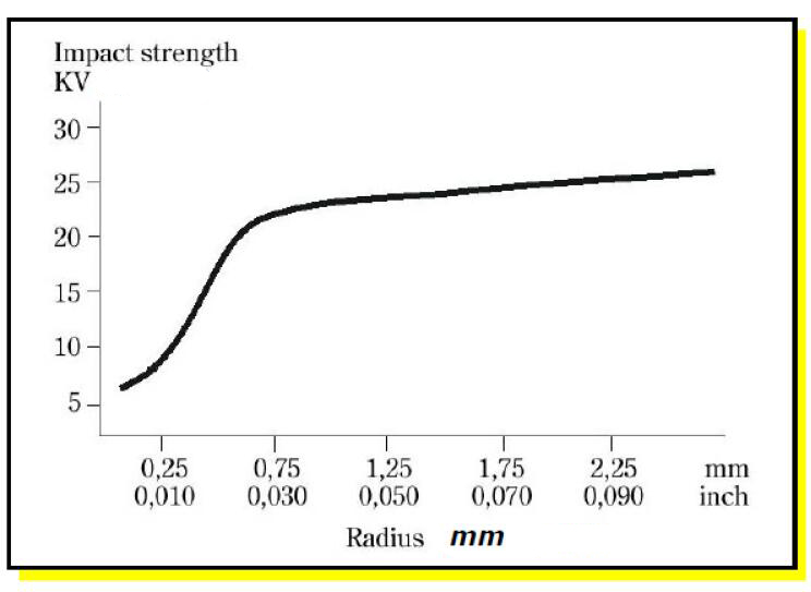
4.4 Recommended radius of casting fillet
- Aluminum alloy>0.04inch(1mm)
- Copper alloy>0.06inch(1.5mm)
- Zinc alloy>0.02inch(0.5mm)
4.5 Use inserts for vulnerable parts
In the case where the product mold allows, for places with a relatively short life expectancy, the block structure is used to prevent the overall scrapping and cause huge losses—for example, small cores and parts where the gate directly impacts.
4.6 Adopt a reasonable mold process:
Small molds should pass through the following:
- Rough machining
- Heat treatment
- Finishing d
- EDM machining
- Nitriding
Large molds should pass through the following:
- Rough machining
- Stress relief tempering
- Semi-finishing
- Heat treatment
- Finishing
- EDM machining
- Nitriding
4.7 Avoid over-polishing
If the surface of the mold is polished like a mirror surface, it is easy to cause the bonding of aluminum and iron, and the surface of the mold will form pinholes. Therefore, it is not necessary to polish the surface of the mold very lightly.
4.8 Nitriding process
In the nitriding process of the mold, the thickness of the nitrided layer needs to be controlled. The excessively thick nitride layer will fall off the parting surface, and the sharp corners and the casting process will be scratched during demolding.
Recommended Nitride Layer Thickness
- Inserts up to 0.05mm
- Core Max 0.13mm
- Sprue sleeve max 0.3mm
4.9 Avoid leaving EDM white layer on the cavity surface

Rough EDM machining to avoid “sparking” and excessive metal removal rates. Fine EDM machining with low current and high frequency.
- Sanding and polishing to remove the EDM layer
- Stress relief tempering at a temperature 25°C lower than the previous tempering temperature
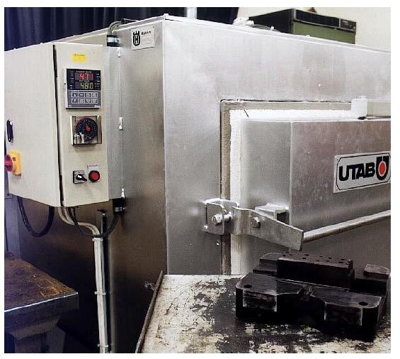
4.10 At the beginning of production, the mold needs to be preheated to a certain temperature. It can be heated by gas flame or mold temperature machine.
Use low filling speed to raise the mold temperature in the first few molds.
4.11 The filling speed should not be too high. High filling speed will only increase the erosion of the mold. Design a reasonable gate area so that the filling speed is less than 55m/s. The typical filling speed range is 30 to 40m/s
4.12 On the premise of ensuring the quality of castings, try to reduce the temperature of the molten metal.
4.13 Do not spray the mold release agent for too long, which will cause the temperature of the mold surface to change drastically. It is best to spray a mold release agent and blow air alternately.
4.14 After the mold is used for a period of time, stress relief treatment is required to prolong the service life of the mold.
Do stress relief once every 5,000 mold times, and then do stress relief treatment every 10,000 to 20,000 mold times
4.15 After the mold is welded, the stress should be relieved in time to ensure that the hardness of the base material and the welding area is greatly reduced.
4.16 Cool the mold the right way
- If cooling with water, preheat the water temperature to 30°C; it can be 40°C in winter.
- Reduce the amount of mold release agent sprayed so as to avoid mold temperature dropping too low.
- Do not turn on the cooling water while the mold is preheating.