
Mold heat treatment process
Recall that the mold is a piece of vital equipment for a successful die casting process. It’s common practice that the mold goes through heat treatment. As a result, we need to discuss the mold heat-treatment process.
There are eight crucial sections for this process, and they are;
- Selection of heat treatment equipment
- Mold risk assessment before heat treatment
- Principle of heat treatment furnace installation
- Control of preheating and heating process
- Austenitizing process control
- Quenching and cooling process control
- Tempering process control
- Metallographic grading standard of die-casting mold after heat treatment
General Steel Microstructure: Metallographic Structure-Organization
- Ferrite –bad for HPDC cavities
- Cementite-bad for HPDC cavities cementite – a harmful structure of die casting mold
- Pearlite–bad for HPDC cavities
- Austenite –High temp microstructure
- Martensite= Goal for HPDC cavity steel
Die Casting Die Steel Performance Requirements
Die-casting molds work in the environment of high temperature, high pressure, high-speed flushing, rapid cooling, and rapid heating, so the die-casting molds are required to have;
- Good resistance to high-temperature tempering – high-temperature resistance
- Good impact toughness – high-pressure resistance
- Good abrasion resistance and erosion resistance—resistance to high-speed erosion
- Good thermal fatigue resistance and crack resistance – resistance to shock and heat for a long time to cycle
The choice of mold steel with good performance is the basis, and heat treatment is a key factor in ensuring mold performance, which directly affects the service life of the mold.
Heat treatment quality problems caused by heat treatment equipment problems or improper processes are often an important factor leading to the early failure of die casting molds. This paper mainly discusses the problems and factors related to mold heat treatment.
Die steel’s most critical heat treatment parameters are austenitization and cooling rate. Cooling rates must be tightly controlled to reduce the risk of deformation and cracking while obtaining the highest quality metallurgical properties.
1.Selection of Heat Treatment Equipment
A.Vacuum equipment Vacuum furnace
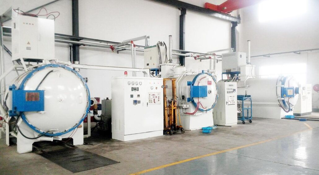
Vacuum equipment is used to prevent the oxidation and decarburization of alloy elements during high-temperature heating and heat preservation, reducing the mold’s performance and causing early cracking, collapse, erosion, and other failures.
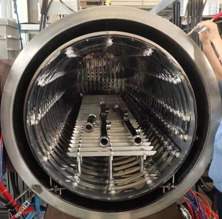
B.The furnace temperature is uniform
The uniform furnace temperature of the quenching equipment can effectively prevent the mold from overheating, over-burning, or insufficient austenitization and other factors, resulting in uneven hardness of the mold, early erosion, cracking, or cracking and scrapping.
The tempering furnace’s uniform temperature can ensure the mold’s uniform hardness, the stress can be fully eliminated, the tempering structure is stable, and the early collapse, erosion, and cracking failure of the mold can be prevented.
Regular inspection of furnace temperature uniformity should be used as an important management principle for heat treatment.
C.Equipped with a multi-point temperature measurement device and process parameters can be adjusted at any time
Real-time monitoring of the temperature changes of the core and surface of the mold during the heat treatment process to guide the timely adjustment of process parameters.
The furnace temperature is not equal to the temperature of the mold. Therefore, it is correct to formulate the process based on the temperature of the mold.
D.Sufficient cooling capacity
In order to prevent carbides from being over-analyzed along the grain boundaries and affecting the performance of the die-casting mold, it is required that the mold be cooled as quickly as possible under the premise of controllable deformation and cracking risks during the quenching process. Therefore, the heat treatment equipment must have sufficient cooling capacity.
2.Mold Risk Assessment Before Heat Treatment
Before the mold is formally heat treated, it needs to be checked:
1)Use spark identification to identify the type of steel, and prevent the steel from being mixed in the same quenching furnace.
2)Make a preliminary assessment of the mold as a whole
Determine whether the machining allowance is sufficient?
Is there any risk of deformation resulting in the insufficient margin?
Is there a risk of cracking in a dangerous shape? If there is a risk, take appropriate action:
For the risk parts that can be reworked to eliminate, promptly request the mold factory to rework to eliminate hidden dangers
- Local protection of hazardous areas
- Special furnace loading arrangements should be made for molds with higher risks
- Make special process arrangements for molds with higher risk
3.Principles of Furnace Charging for Heat Treatment
When it comes to furnace charging, the following principles must be given utmost adherence.
1)Different steel types are not mixed together
2)Do not mix if the size difference is too large
3)Do not mix with different performance requirements
4)The molds in the furnace should be placed reasonably to ensure uniform heating and quenching cooling
5)The geometry of the mold should be considered to ensure the uniformity of heat treatment and prevent the mold from deforming too much and cracking
6)The loading should not be excessive to ensure that the furnace can meet the minimum cooling rate requirements (≥28° per minute)
7)Place thermocouples in the mold with the largest cross-section and in the center. For molds with a high risk of deformation and cracking, it is recommended to place thermocouples on the core and surface.
4.Preheating Process Control
The following scenarios are typical of the preheating process.
- Heating speed Preheat at a heating speed of ≤220°/hour
- The furnace temperature rises to 675° and keeps heating until Ts-Tc < 110°.
- The furnace temperature rises to 850° and keeps heating until Ts-Tc < 60°.
Or, according to actual needs, carry out multi-stage preheating and heat preservation so that the temperature difference between the core and the surface of the mold is minimized, and the thermal stress of the mold is reduced to prevent deformation or cracking.
5.Austenitizing Process Control
A.Determination of austenitizing temperature
The determination of the austenitizing temperature should be determined according to the use of the mold. This is because the purpose of austenitizing and making the temperature of each part of the workpiece uniform is mainly to dissolve carbides and increase the effective alloy content in the matrix.
Take 2344 and 8407 as examples, as below:
When the austenitizing temperature is 995~1010°
The advantages include:
- High impact toughness
- Small deformation
The disadvantages include:
- Poor softening resistance at high temperature
- Easy to crack
The uses include:
- It is suitable for molds with a low die casting temperature
- Complex cavity and easy deformation and cracking
When the austenitizing temperature is 1025~1035°
It has the advantage of balanced performance and is used for conventional processes.
When the austenitizing temperature is 1040~1050°
The advantages include:
- Carbide is fully dissolved,
- Better resistance to high temperature softening
- Better resistance to thermal fatigue cracking
The disadvantage includes:
- Poor impact toughness
- Easy to crack
Usage:
Suitable for molds with high die casting temperature and relatively simple shape, with strong resistance to erosion, collapse, and cracking.
B.Determination of the austenitizing time
The principle of the austenitizing holding time is to make the core and surface temperature of the mold uniform (to prevent excessive quenching deformation). Also, to fully dissolve the carbides to increase the effective alloy content in the matrix (to ensure the performance of the mold), but also to prevent crystallites—grain growth (reduces mold performance).
The recommended austenitizing holding time is: 30 minutes after Ts-Tc<14°, or a maximum holding time of 90 minutes after Ts reaches the specified temperature
Ts refers to mold surface temperature Tc refers to mold core temperature
6.Quenching and Cooling Process Control
A.The cooling rate determines the organizational structure
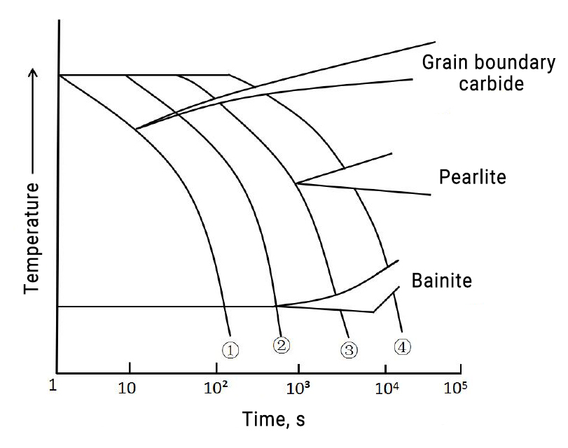
Choosing a faster cooling rate results in a better microstructure, but the risk of deformation and cracking increases. Before formulating a quenching process, a risk assessment of the mold must be carried out to achieve the best balance between performance and risk.
- Full martensite, ideal structure, not possible to achieve by cooling too fast
- Martensite + a small amount of grain boundary carbide structure, small molds can be realized
- Martensite + bainite + part of grain boundary carbide structure, the quenching structure requirements of medium and large molds are also the basic requirements of die casting molds for quenching equipment and cooling strength of quenching medium.
- The structure contains a pearlite structure. Although the hardness can meet the requirements after tempering, it reduces the impact toughness and thermal fatigue resistance of the die-casting mold, resulting in early failure of the mold.
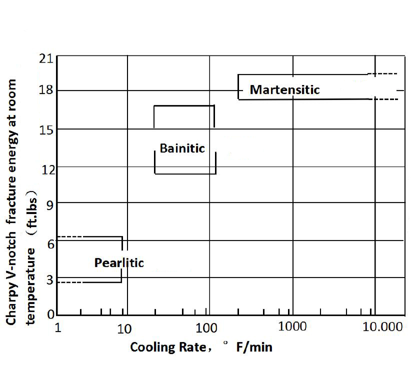
B.The effect of cooling rate on toughness
The pearlite, bainite, and Martensitein in the figure correspond to the curves 4 3 2 in the figure above, which intuitively reflects that the faster cooling rate can avoid the increase of bainite and the appearance of pearlite, thereby improving the toughness.
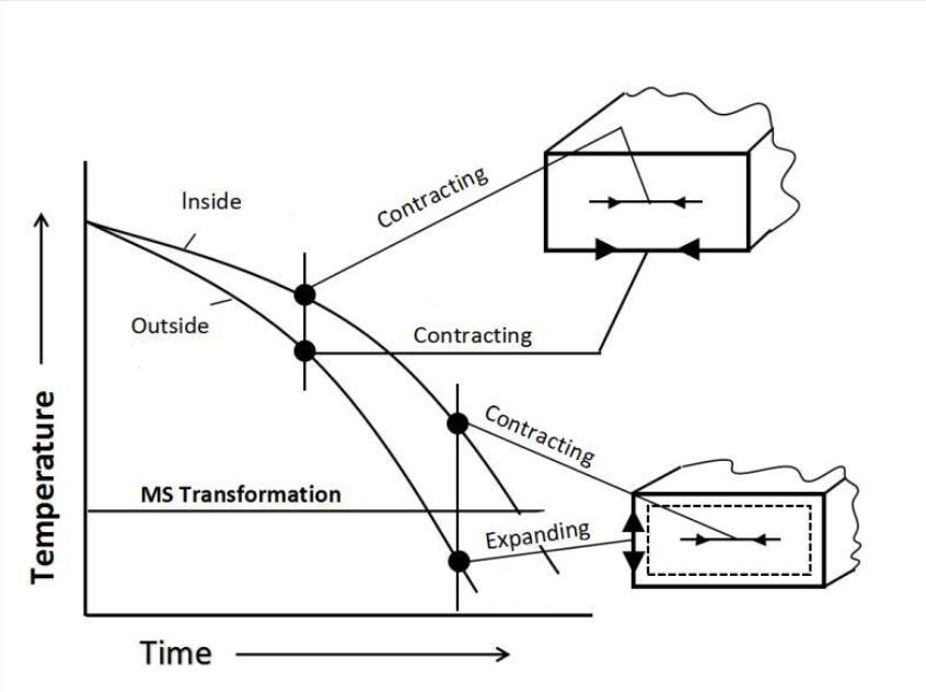
C.During the cooling process, the stress of the mold changes.
The surface always cools faster than the core. Therefore, the mold surface and corners shrink faster than the core above the martensitic transformation temperature. In contrast, at lower temperatures, the mold surface transforms into martensite or bainite and expands while the core is still at the transformation temperature above the shrinkage continues.
When the core falls below the martensitic transformation point, the core undergoes martensitic transformation and expands, and the surface shrinks due to the temperature drop.
It can be seen that the stress of the mold changes continuously with the change of temperature and the stress difference between the core and the surface increases with the increase of the temperature difference. In addition, the shape factor of the mold itself may cause the stress to superimpose and cause the mold to deform or deform.
D.Adopt processes such as isothermal quenching to prevent mold deformation and cracking
The use of isothermal quenching or staged quenching can reduce the degree of deformation and the risk of cracking while maximizing the metallurgical properties, as shown in the figure below.
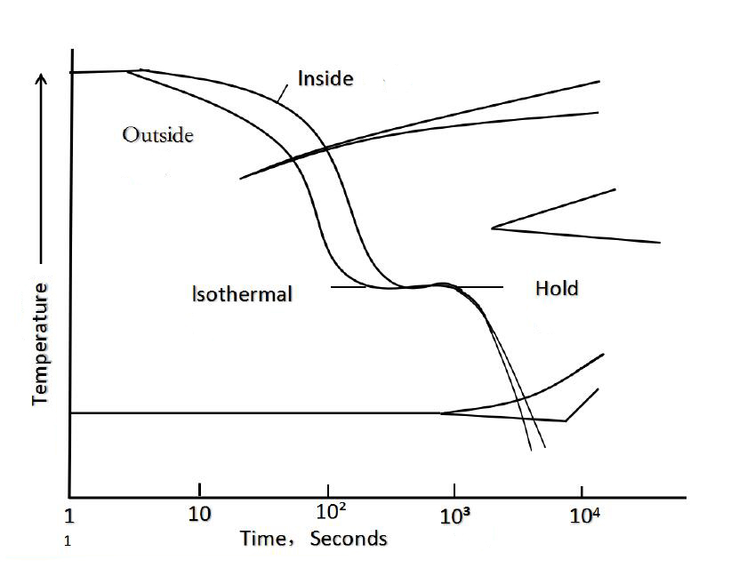
Key points of isothermal quenching operation:
· The initial cooling rate must be fast enough to reduce carbide precipitation at grain boundaries and suppress pearlite transformation.
· Pearlite transformation no longer occurs below 540°C. It can be maintained isothermally between 400-455 °C, so that the temperature of the workpiece surface and the core tends to be consistent, and then continue quenching and cooling. Although the surface still cools faster, the reduced temperature difference reduces the internal stress.
· Excessive isothermal times should be avoided to reduce bainite formation.
E.Quenching out of the furnace
The temperature of the core of the mold is cooled to Tc≤150℃, and it is placed in still air for natural cooling, and the quenching is completed.
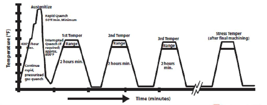
7.Tempering process control
The quenched mold is in a state of hard brittleness and high-stress instability, which is prone to brittle cracking. Therefore, when Ts≤50℃, it must be tempered in time.
A.Purpose of tempering
- Reduce the internal stress caused by quenching
- Promote the decomposition of retained austenite and stabilize the mold size
- Transformation of untempered martensite into tempered martensite by precipitation of complex carbides
- Obtain the hardness required by the mold, improve the toughness and crack resistance of the mold
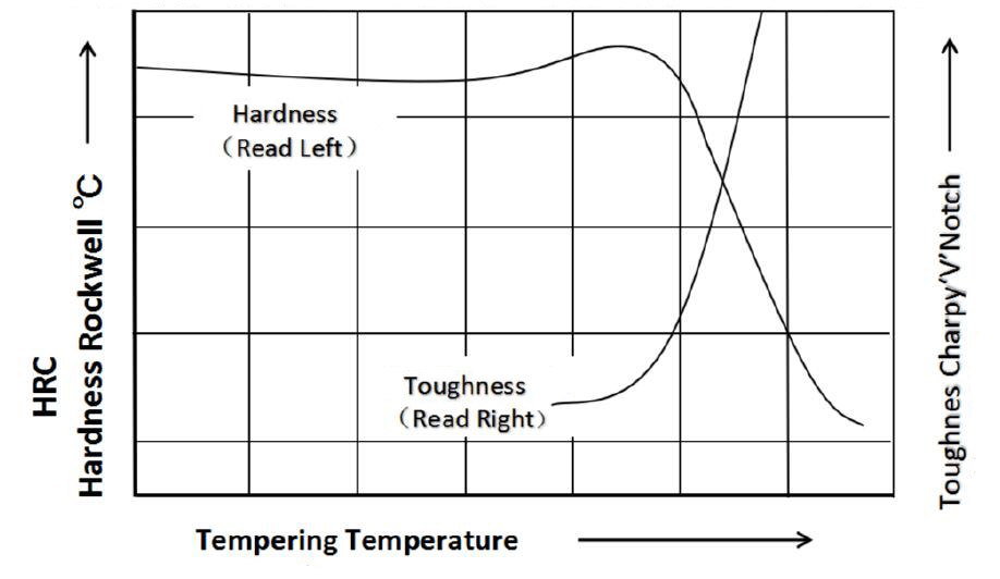
B.Tempering requirements
- Uniform furnace temperature (≤±5℃) to ensure uniform mold hardness
- The tempering temperature should be avoided as far as possible in the secondary hardening peak area (brittle zone) of the mold
- Hardness required to achieve mold application: since the hardness of the mold is closely related to the chemical composition of the material, the heating temperature of quenching, the holding time and the cooling rate, etc. For a more uniform mold hardness, a longer holding time is preferable to a higher tempering temperature
- Avoid high-temperature charging and rapid heating to prevent mold cracking and deformation
- Sufficient tempering time: the holding time of the mold core is at least ≥2 hours after the temperature is reached (the holding time should be as long as possible when conditions permit)
- The number of tempering times should not be less than 2 times, and the number of tempering times for complex molds and medium and large molds should be at least 3-4 times to obtain the best stability, toughness, and tempering resistance
- In the end, the stress relief is sufficient. The structural transformation is sufficient, and the dimensions are stable; the mold has no deformation. Cracking risk and comprehensive properties such as toughness, high-temperature tempering resistance, erosion resistance, and crack resistance (thermal fatigue) are guaranteed and improved.
- After finishing the mold is finished, a stress relief tempering is required to eliminate the machining stress after finishing (especially electric discharge machining) to ensure the mold’s performance in the production process.
8.Metallographic Grading Criteria for Die Casting Moulds After Heat Treatment
The North American Die Casting Association (NADCA) has put forward a clear inspection standard for whether the metallographic structure of the die-casting mold after heat treatment is qualified, as shown in the following figure
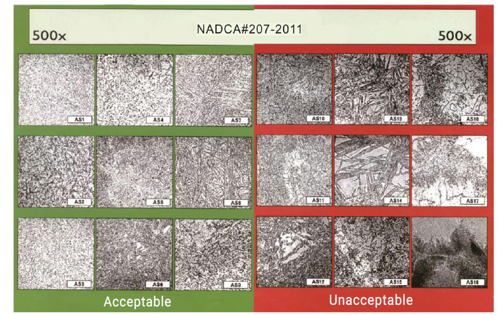
- The above metallographic diagram is the result of corroding H13 with 5% nitric acid alcohol solution after proper heat treatment and observing it under a microscope of 500 times. It is also applicable to the judgment of heat treatment quality of A-F grade other die-casting die steel.
- HS1-HS9 are all qualified microstructures, and the difference in the number does not indicate the quality level. This change in microstructure is common, partly because of the different thicknesses of the heat treatment modules, and may also be qualified by different original annealing caused by microtissues.
- The microstructure shown in HS1-HS9 is mainly composed of tempered martensite, with different contents of bainite and needle-like structures of different sizes and different contents of grain boundary carbide precipitation.
- HS10-HS18 are unqualified heat treatment structures. HS10 and HS11 have a decrease in material properties due to the precipitation of pearlite (dark islands) at the grain boundaries. This is all the result of the slow cooling rate of heat treatment and quenching.
- HS12 is due to the extremely slow cooling rate of quenching, which causes the steel to start annealing. An annealed structure similar to island ferrite + spherical carbide is formed, which obviously cannot provide the performance required for die casting.
- HS13, HS14, HS15—There are different degrees of chain precipitates and dark etched areas in these 3 pictures. This situation is not caused by improper quenching and tempering heat treatment. These are actually “congenital defects” brought by the original material that heat treatment cannot modify, such as liquid segregation and severe segregation.
- HS16 shows the three-layer structure on the surface, which is the result of heat treatment of the mold in an ordinary heating furnace (austenitizing and heat preservation in a non-vacuum state). The gray layer at the top is the surface oxide (scale); the middle part of the dark etching is grain boundary oxidation; the light etching area at the bottom is the decarburization area. The lowermost matrix structure contains carbides precipitated at the grain boundaries and is a typical (normal) result of H13 steel quenched in air.
- HS17—shows that the austenitization temperature of mold heat treatment is too low (below the recommended range temperature). The microstructure is obtained by insufficient austenitization. The microstructure is unclear, and the features cannot be distinguished.
- HS18—Shows the microstructure obtained after the mold is austenitized (or austenitized for a long time) at a temperature higher than the recommended range. This microstructure has coarse grains (ASTM grade 3) and a coarse martensitic matrix.